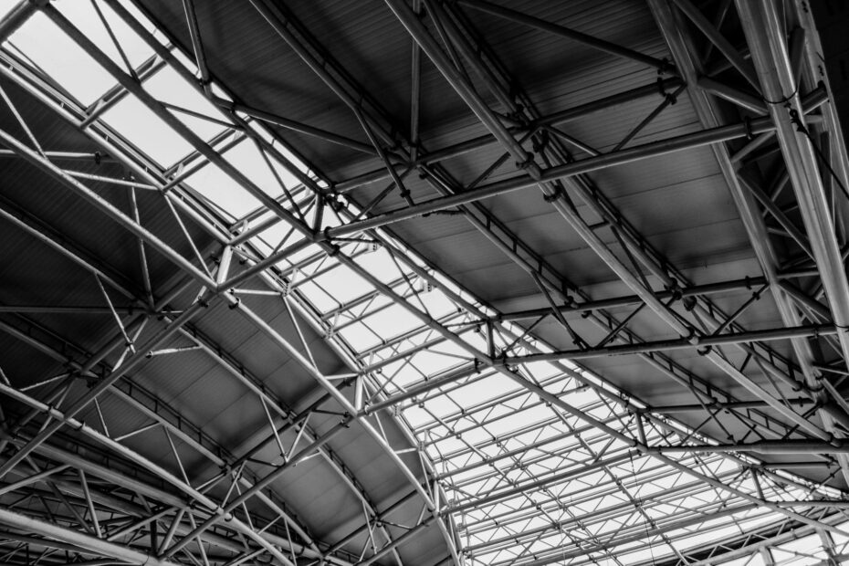
Engineered triangular lumber assemblies carry roof weight through planned bearing points using straight members arranged to share loads. Your roof may look like one broad surface, yet every top chord, bottom chord, and web member has a specific job within the frame.
This explanation covers truss parts, force flow, spans, bracing, roof shapes, and alteration limits for your home, remodel, attic access plan, or new roof project.
Triangular Framing Directs Roof Weight to Bearing Points
A rectangle can rack into a diamond under sideways force. Add one diagonal member, and the shape resists that movement. Roof trusses use the same geometry, with triangulation directing roof forces through straight lumber rather than relying on a large solid beam over every room.
Your truss sits below the shingles, metal panels, underlayment, and roof decking. Those layers collect weather exposure and weight. The frame below sends that weight toward bearing walls, beams, footings, and soil.
Triangulation Resists Shape Changes
Triangles hold their shape because each side restrains the other two. Under gravity loading, one member can shorten in compression while another stretches in tension. That push-and-pull arrangement lets your roof frame carry substantial force with smaller lumber pieces than a comparable solid member.
A king post truss has a central vertical member that divides the frame into two triangles. A Warren truss uses repeated diagonals instead. You do not need to identify every truss pattern in your attic, but each diagonal belongs to a calculated route for force.
| Part of the roof system | What it does for your home | Where its force goes |
|---|---|---|
| Roof covering | Shingles, panels, and underlayment shed weather and add dead load. | Roof decking receives that weight. |
| Roof decking | Sheathing spreads surface loads across several framing members. | Top chords receive the transferred load. |
| Roof truss | The triangular frame redirects forces through chords and webs. | Bearing points deliver force to walls or beams. |
| Structure below | Walls, beams, foundation, and soil resist accumulated roof load. | Site soil receives the final downward force. |
That distinction matters during a remodel. Your roof surface can look sound while a damaged chord below has lost structural capacity. A plain-looking wall can also carry the bearing reaction from every truss above it.
Those concentrated reactions only make sense when each chord and web performs its assigned role.
Typical Truss Members Have Separate Structural Jobs
The outer sloped pieces in an unfinished attic trace the roof line. Those members are the top chords. Their angle follows the roof pitch, while their lumber grade, length, and joint details come from the truss design drawing.
Your bottom chord runs across the base of a standard residential profile. It can frame the ceiling below, yet it also resists the outward force produced by loaded top chords. That tension role makes the horizontal member just as structurally serious as the sloped pieces above it.
Chords, Web Members, and Heel Joints Form the Frame
Web members are the interior diagonals and verticals. They route force between outer chords and divide a long truss span into shorter segments. Shorter compression pieces resist bending and sideways buckling more effectively than a long unbraced member.
At each lower corner, the heel joint joins a top chord to the bottom chord near a bearing point. Your truss can bear at that heel on an exterior wall. Raised heels, interior bearings, and deeper end details appear on designs that need room for insulation or unusual loading.
| Truss component | Structural role in your roof | Field clue for your inspection |
|---|---|---|
| Top chord | The sloped outer member carries roof loads toward the ends. | It sits directly under roof sheathing. |
| Bottom chord | The horizontal member resists spreading forces and frames the ceiling. | It runs from one lower end to the other. |
| Web members | Interior diagonals and verticals route forces between chords. | They form smaller triangles inside the frame. |
| Heel joint | The lower corner transfers force near the planned bearing. | It sits above a wall or beam line. |
| Connector plates | Toothed metal plates lock member ends into a designed joint. | They appear on one or both faces of a joint. |
Metal connector plates are also called gusset plates in casual jobsite speech. A hardware-store angle bracket is not an interchangeable replacement. Plate size, tooth pattern, placement, lumber overlap, and joint geometry all affect the force a joint can carry.
Never pry out, bend, or cover a connector plate with a field-installed fastener pattern. A plate that has lifted from the lumber needs review by a qualified truss designer or structural engineer.
Compression and Tension Carry Loads Through the Frame
Gravity load does not stop at the roof deck. Rain, snow, roofing materials, ceiling finishes, and maintenance activity enter the framing and move downward. You can trace that route from the roof surface to the soil below your foundation.
Roof Loads Follow a Continuous Route
The roof truss load path starts with shingles, tile, metal roofing, or another exterior covering. Roof sheathing sends those forces to the top chords. The top chords direct force through web members and joints, then into bearing points at walls or beams.
Below those bearing points, load enters wall studs, posts, headers, girders, or foundation elements. Your foundation spreads the reaction into soil. A weak connection in that route can appear as cracked drywall, a sagging roof plane, or doors that rub their frames.
- Roof surface Roofing and weather loads press on roof sheathing across the sloped plane.
- Top chords Sloped chords carry much of the gravity force as compression.
- Web members Interior pieces redirect force through shorter routes inside the frame.
- Bearing locations Heel joints or specified interior points send reactions to walls or beams.
- Ground below Foundation elements and soil receive roof force after it moves through the structure.
Load Direction Changes Member Forces
Under gravity loading, top chords work mainly in compression. Their wood fibers squeeze together, much like a short block pressed between two hands. Long compression members can bow sideways before the fibers crush, which explains the bracing rules used during installation.
Your bottom chord is commonly in tension under the same gravity condition. It acts as the tie at the base of the triangle and resists outward wall spread. Remove or weaken that tie, and the geometry holding exterior walls in position changes immediately.
Web forces can be less obvious. One diagonal can carry compression under snow load and experience a different stress pattern under wind uplift. Your truss drawing accounts for dead load, roof live load, snow or rain load, wind, and short-duration maintenance loading.
Wind can reverse part of the normal force direction. Uplift pulls upward on the roof surface and places demand on connector plates, truss-to-wall anchors, and the wall system below. Your hurricane clips matter because a roof must resist upward lift as well as downward weight.
Whether loads push downward or pull upward, they still need a continuous path into adequate supports.
Bearings and Span Limits Set the Structural Layout
A broad living room can sit below a roof without a central bearing wall because many residential trusses span from exterior wall to exterior wall. That clear room width is one reason trusses appear in garages, ranch homes, and wide open floor plans.
Your interior wall does not carry roof load simply because it touches the ceiling. A nonbearing partition can sit below bottom chords without receiving truss reaction. An interior wall or beam becomes structural only where the truss drawing marks it as a bearing line.
Planned Bearing Locations Cannot Shift
Every truss has assigned bearing points. Moving a bearing wall, lowering a beam, cutting a post, or leaving a planned bearing without solid framing changes how force enters the truss. Your roof can crack or deflect even though the lumber still looks intact.
Long spans, concentrated roof loads, girder trusses, attic rooms, and complex hip intersections can need interior reactions. A girder truss carries other trusses framing into it, so your plan can place several roof reactions at one post or beam rather than spreading them along a wall.
| Design factor | Effect on your span capability | Why your drawing matters |
|---|---|---|
| Roof pitch | A steeper profile changes chord angles and internal forces. | The engineer sizes members for that geometry. |
| Truss spacing | Spacing changes the roof area carried by each frame. | The layout can show 16, 19.2, or 24 inches on center. |
| Snow and wind zone | Climate changes gravity and uplift demands. | Design criteria match the job location. |
| Lumber and depth | Wood grade and member size affect compression and tension capacity. | Stamped truss data identifies the selected materials. |
| Added equipment | Solar arrays and mechanical units add concentrated force. | The truss designer checks the altered loading pattern. |
No universal number answers how far roof trusses span without intermediate bearing. Your truss span depends on geometry, spacing, wood grade, design load, connection capacity, and bearing arrangement. A 24-foot common truss and a 36-foot attic truss use very different structural arrangements.
Your ceiling line is not proof that a wall carries roof load. Find the truss placement plan and bearing symbols before removing walls, opening a ceiling, or placing a beam beneath a chord.
Roof Shape and Room Plans Change Truss Design
That bearing layout leads directly to truss shape. A low-slope shed roof, a gable roof with flat ceilings, and a vaulted great room place different geometric demands on the framing above your rooms.
Common Profiles Match Different Roof Forms
A common truss fits a basic gable roof and flat ceiling. A fink truss uses a dense W-shaped web pattern for residential spans. A mono truss carries a single roof slope, while hip trusses handle changing roof directions at a hipped end.
Your roof plan can also use girder, valley, and jack trusses around hips and valleys. These pieces do not carry equal loads. A girder frame can receive several attached trusses, so its bearing reaction needs careful framing below.
| Truss profile | What it gives your layout | Tradeoff for your attic |
|---|---|---|
| Common truss | A gable roof receives a simple flat-ceiling profile. | The web network limits open storage space. |
| Fink truss | A moderate residential span uses repeated interior webs. | The central attic area remains obstructed. |
| Scissor truss | A room gains a sloped or vaulted ceiling. | Changed bottom chord geometry raises design demands. |
| Attic truss | The roof frame encloses a planned room or storage area. | The deeper profile uses more material and planned floor loading. |
| Mono truss | A single-slope roof frames a shed, addition, or clerestory. | The high end can place concentrated load at one bearing area. |
Usable Attic Space Needs Its Own Design
An attic truss is not a standard truss with a few webs removed. Its room opening, floor chords, side walls, and roof members form a separate engineered arrangement. Your future bedroom, office, or storage plan needs floor-load capacity designed into the frame from the beginning.
A scissor truss creates a vaulted ceiling by raising the bottom chord into a shallow V. That ceiling shape changes force directions and can raise bearing reactions. Your exterior walls, tie details, and insulation plan must fit the selected profile.
Solar panels add dead load and wind exposure. Suspended HVAC units add point loads. Deep snow drifts beside taller roof sections can focus weight in narrow areas. Your contractor needs truss data before attaching equipment or hanging mechanical items from a bottom chord.
Trusses and Rafters Involve Different Framing Tradeoffs
Factory-built trusses arrive as repeated engineered units, while conventional rafters are cut and fitted on site. Your choice affects attic access, labor sequence, lifting needs, future changes, and the shape of rooms below.
| Framing approach | What your project gains | What your project gives up |
|---|---|---|
| Roof trusses | A crew can set repeated frames across broad spans. | Attic webs restrict storage and later changes. |
| Site-cut rafters | Framing can adapt around unusual roof shapes and openings. | The crew spends more time cutting, fitting, and aligning lumber. |
| Attic trusses | The plan reserves framed room above. | The deeper frame needs larger members and planned bearings. |
| Stick-framed roof | Future ceiling or attic revisions have more open space. | The layout needs separate ties, beams, or rafter ties. |
Trusses Favor Repeated Layouts and Clear Rooms
The roof trusses vs rafters choice is not about one framing method being better in every house. Trusses fit repeated bays, wide interior rooms, and predictable roof geometry. Rafters fit unusual shapes, dormers, field changes, and attic work that would conflict with internal webs.
Material use is another difference. A truss directs force through several short pieces, reducing the need for long solid lumber in some designs. Your project still needs truck access, dry staging space, lifting equipment, and a controlled setting sequence.
- Web restrictions Attic storage routes can be blocked by diagonals that cross the center of the frame.
- Delivery size Long assembled frames need clear truck access and protected staging space.
- Lifting needs Large spans can need a crane, boom, or mechanical lift during placement.
- Change limits Plumbing, wiring, and storage openings cannot cut through engineered members.
- Repair review A damaged truss needs engineered repair details rather than a casual sister board.
Those limits do not make trusses weak. They make the framing specific to its planned loads, joints, bearings, and bracing. Your roof works as a coordinated structural arrangement rather than as separate pieces of lumber.
Bracing Holds the Frame Stable During Installation
A truss lying flat in a delivery stack behaves differently from a truss standing on walls. Before roof sheathing ties the assembly together, a tall slender frame can roll, lean, or buckle under its own weight and wind exposure.
Temporary Bracing Holds the Layout in Place
Your installation crew sets the initial truss plumb, braces it, and then sets the next frames at the layout marks. Temporary lateral braces and diagonal braces hold alignment across the roof until enough framing and sheathing form a stable diaphragm.
Spacing errors can multiply across a roof. A truss set one inch off layout at one end can shift roof sheathing joints, fascia lines, and later trusses out of position. Your crew should follow the placement diagram rather than stretch layout from visual guesswork.
Permanent Restraint Limits Buckling
Compression members need lateral restraint because a thin piece of lumber can bow sideways before its fibers crush. Your top chords and selected web members receive continuous lateral restraint, blocking, or bracing at locations shown in the truss package.
Roof sheathing adds restraint across top chords. Ceiling drywall can add restraint at bottom chords after installation as planned. Neither finish layer replaces truss bracing because manufacturer instructions identify which individual members need direct restraint.
- Review layout sheets The placement plan identifies spacing, bearing marks, special truss labels, and setting order.
- Brace the starter The initial frame needs temporary restraint before adjacent units leave lifting equipment.
- Keep frames plumb Aligned trusses reduce roof-plane waves and unintended bending during erection.
- Install restraint lines Compression webs need lateral restraint at marked locations.
- Add diagonal bracing The roof plane needs diagonal members that stop long rows from racking sideways.
- Follow design notes Project documents govern bracing details, fasteners, and installation sequence.
The International Residential Code sets broad residential framing rules, while truss design packages carry job-specific information. Your local jurisdiction can request stamped documents or inspection records for long spans, high-wind areas, and complex roof geometry.
That documentation becomes essential when a proposed field change could redirect forces through the assembled roof.
Alterations Need Engineering Rather Than Field Changes
A two-inch hole through the wrong web can interrupt a force route that crosses the entire roof. Cutting, drilling, notching, removing, moving, or splicing a truss member without written engineering direction can leave your frame unable to carry its planned loads.
Your attic can present tempting reasons to alter framing: a bath vent, large duct, pull-down stair, storage access, wiring route, skylight opening, or new air handler. None of those uses shows whether a member has unused structural capacity.
Small Cuts Can Cause Larger Structural Problems
Drilling through a tension chord removes wood from a member that resists stretching. Cutting a compression web can leave another member longer and more prone to buckling. Your damage may stay out of sight at first, but snow, wind, or ceiling loading can expose the weakened route later.
Cracked drywall at wall corners, a sagging chord, connector plates pulling away, split lumber near a joint, or doors that begin to bind deserve prompt review. Your roof framing can also hide damage after a water leak, fallen tree limb, or misplaced equipment load.
Do not use a field-made plywood patch, metal strap, or added board as a truss repair unless a qualified designer supplies the repair drawing and fastening schedule for the damaged location.
Documentation Guides a Repair Decision
Locate the truss design drawing, placement plan, and any tag near a truss end. Your records identify the truss profile, spacing, design loads, bearing layout, and special girder locations. A truss manufacturer can sometimes identify a package from labels or job records.
- Stop cutting Pause the opening or repair before any member loses material or changes shape.
- Photograph damage Photos should show the full truss, close joint details, bearing area, and nearby equipment.
- Find drawings The placement sheet and truss profile show member labels and design geometry.
- Document loads List solar panels, storage, HVAC units, snow exposure, and roof additions.
- Obtain repair details A structural engineer or truss designer can specify lumber, plates, bolts, screws, and fastener spacing.
- Install as drawn The repair crew must follow the supplied detail without field substitutions.
The Structural Engineers Association publishes professional resources that reinforce a basic rule: structural repairs need a known force route. Your truss drawing governs that route; it is not a rough sketch for field changes.
Final Thoughts
Your roof stays stable because each truss directs gravity and wind forces through assigned members into assigned bearings. The triangles use lumber efficiently, yet they do not tolerate random cuts, missing restraint, moved walls, or added equipment loads.
Once you see how a roof truss system works as a continuous route from roof decking to soil, your next construction choice becomes clearer. Preserve the engineered route, or obtain a designed revision before changing the framing.
FAQ
How does a roof truss system work?
Triangular lumber members transfer roof loads from sheathing into top chords, web members, and planned bearing points. Your bottom chord resists wall spread, while walls, beams, foundation elements, and soil carry the final reactions below the roof frame.
What are the top chord, bottom chord, and web members of a truss?
The top chord is the sloped outer member below roof decking, and the bottom chord runs across the ceiling line. Your web members are the interior diagonals and verticals that route force between those chords. Connector plates join the lumber at designed joints.
Do roof trusses need load-bearing walls?
Design drawings specify the required bearing locations, so a central load-bearing wall is not always necessary. Many residential trusses span between exterior walls. Your plan can still need interior beams, posts, or walls for girder trusses, long spans, or concentrated reactions.
How far can roof trusses span without intermediate bearing?
No single span number fits every roof truss. Your allowable distance depends on roof pitch, truss spacing, lumber grade, web pattern, snow load, wind load, roof weight, connection details, and bearing layout. Your truss drawing gives the span and bearing arrangement for that project.
What is the difference between roof trusses and rafters?
Factory-built triangular frames use internal webs, whereas rafters are individual sloped members cut and assembled on site. Your truss layout can span wide rooms efficiently, while rafters can leave more open attic space for future changes.
What are the downsides of a truss roof?
Interior web members can restrict attic storage, conversions, duct routes, and future ceiling changes. Your project also needs delivery access, lifting planning, bracing during installation, and engineered details for later repair or modification.